Hardware & Wiring
This section is the field-installation reference for the AccessCore One access controller — the controller behind every current CloudAccess Key site. It covers how to power the board, wire readers, locks, request-to-exit devices, door contacts, and the fire alarm input, and how to get the controller on the network.
It's written for dealers, installers, and field technicians. It assumes you install low-voltage security systems for a living.
:::caution Qualified installation only
Install and service this equipment only if you are a qualified low-voltage technician. De-energize the controller and any lock power supply before wiring. Run all wiring per the NEC, local electrical and fire codes, and the requirements of the local Authority Having Jurisdiction (AHJ). Life-safety wiring (egress, magnetic locks, fire release) must be coordinated with the fire alarm system — see Fire Alarm Integration.
:::
The controller at a glance
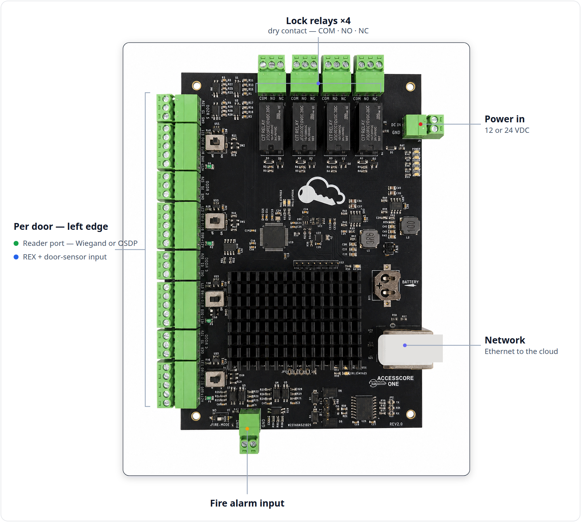
The AccessCore One controller manages up to 4 doors. For each door it provides:
- a reader port — Wiegand or OSDP (RS-485), selectable per port;
- a lock relay — a dry Form C (COM / NO / NC) output for an electric strike or magnetic lock;
- a 3-pin input port — request-to-exit (REX) plus a door position sensor (DPS).
Site-wide it adds a fire alarm input that releases the doors for egress, an Ethernet uplink to the CloudAccess Key cloud, and battery backup (from the listed power supply) so access keeps working through a mains outage.
A split design keeps doors live during cloud reconnects and updates: an on-board node runs the application and holds the offline access database, while a dedicated control MCU drives the door I/O. A battery-backed real-time clock preserves schedules and event timestamps through power loss.
Wiring guides
Work through these in order on a new install, or jump to the one you need:
- Controller Overview — board anatomy: every connector, jumper, and status LED, and what each port is for.
- Listing & Compliance — UL 294 installation conditions: enclosure, listed power supply, fused relay outputs, and independent egress release.
- Power & Enclosure — 12 or 24 VDC input, battery backup, cooling fan, grounding, and current budgeting.
- Wiring Readers — Wiegand and OSDP readers, the OP/WD protocol jumper, fuses, and cable runs.
- Wiring Locks — Form C relay outputs, fail-safe vs fail-secure, strikes vs maglocks, and surge suppression.
- REX & Door Contacts — request-to-exit devices and door position sensors.
- Fire Alarm Integration — the fire input, the FIRE_MODE jumper, and releasing locks safely.
- Networking & OSDP Bus — Ethernet uplink and the RS-485/OSDP reader bus with termination.
- Terminal & Connector Reference — the full pin-by-pin cheat sheet plus a first power-up checklist.
:::tip One board, one wiring story
All current AccessCore One controllers wire the same way — the terminals, jumpers, and pinouts in this section apply across the board family. You don't need to identify a board revision to wire it.
:::
Before you start a job
- For a UL 294-compliant install, observe the four conditions on Listing & Compliance: a locked enclosure in the secured premises, a UL-294-listed battery-backup supply, lock outputs through a UL-listed fused relay/output board, and an independent hardware egress power-interrupt for push-to-exit and fire release.
- Plan the lock type per door — fail-secure electric strike vs fail-safe magnetic lock — because it determines whether lock power runs through NO or NC. See Wiring Locks.
- Plan the reader protocol per door — Wiegand or OSDP — and set the OP/WD jumper to match. See Wiring Readers.
- Confirm the fire alarm interface and egress requirements with the fire alarm contractor and the AHJ before energizing. See Fire Alarm Integration.
- Keep the Terminal & Connector Reference open — its commissioning checklist walks the whole board end to end.