AccessCore One Controller Overview
The AccessCore One is a 4-door networked access controller. A single board provides everything needed to control four doors:
- 4 reader ports — one per door (Wiegand or OSDP).
- 4 lock relays — one dry-contact Form C relay per door.
- 4 input ports — one 3-pin REX + door-sensor port per door.
The board also carries a fire-alarm input, an on-board RTC clock battery, a fan header, and an Ethernet uplink to the CAK cloud. Use this page as the hub: each connector group links out to its detailed wiring page below.
Why doors keep working
Internally the AccessCore One uses two processors plus a battery-backed clock. You do not wire any of this — it matters because it changes how the controller behaves during reboots and outages:
- Node — runs the CAK edge application, holds the offline access database, and talks to the cloud.
- Control MCU — drives the relays, reader data lines, and inputs. Because the door I/O runs on its own MCU, doors keep granting and denying access even while the node reboots or applies an update.
- Battery-backed real-time clock — a coin-cell-backed clock keeps schedules and event timestamps correct through a full power loss.
The practical takeaway for the field: the controller does not need internet to run — internet is only needed to make configuration changes. A cloud/internet outage or a software update does not drop the doors; access decisions continue locally. If the node itself goes offline, the control MCU keeps the door working from a master card list until the node returns.
Board at a glance
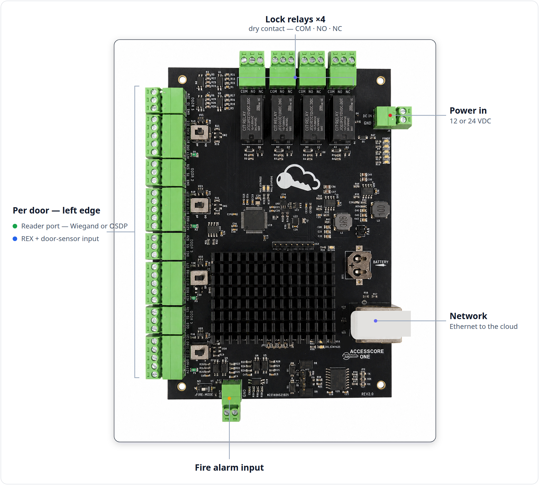
The connectors are grouped by edge. Orient the board with the silkscreen "ACCESSCORE ONE" logo at the bottom-right:
- LEFT edge — the four doors, top to bottom. Each door has a 3-pin input port ("DOOR 1".."DOOR 4") directly above its 5-pin reader port (J14–J17). The reader port carries the per-reader OP/WD protocol jumper.
- TOP edge — the four lock relays (DR1–DR4 / J1–J4), each a
COM NO NCdry-contact set. - RIGHT edge — system and power: DC IN / GND (J9), BATTERY (BT1), FAN header, and the Ethernet RJ45 uplink (J19).
- BOTTOM edge — FIRE input (J13) with its FIRE_MODE jumper, the shared GND terminal block, and the RS-485 OFF/120 termination jumper.
External connector reference
Every field-wired connector group, in silkscreen terms:
| Group | Silkscreen | Ref | Pins | Purpose | Detail page |
|---|---|---|---|---|---|
| DC power input | DC IN / GND | J9 | 2 | 12 or 24 VDC main power in | Power & Enclosure |
| RTC clock battery | BATTERY | BT1 | coin cell | Backs up the real-time clock through power loss (on-board, not field-wired) | Power & Enclosure |
| Cooling fan | FAN | — | 2 (+ / −) | 12 V fan for the node | Power & Enclosure |
| Network uplink | Ethernet RJ45 | J19 | — | 10/100 link to the CAK cloud | Networking & OSDP Bus |
| Reader port — Door 1 | LED D0/A D1/B GND +12V | J14 | 5 | Reader data + power (Wiegand/OSDP) | Wiring Readers |
| Reader port — Door 2 | LED D0/A D1/B GND +12V | J15 | 5 | Reader data + power (Wiegand/OSDP) | Wiring Readers |
| Reader port — Door 3 | LED D0/A D1/B GND +12V | J16 | 5 | Reader data + power (Wiegand/OSDP) | Wiring Readers |
| Reader port — Door 4 | LED D0/A D1/B GND +12V | J17 | 5 | Reader data + power (Wiegand/OSDP) | Wiring Readers |
| Door input — Door 1 | RX1 S1 GND | J5 | 3 | REX + door sensor | REX & Door Contacts |
| Door input — Door 2 | RX2 S2 GND | J6 | 3 | REX + door sensor | REX & Door Contacts |
| Door input — Door 3 | RX3 S3 GND | J7 | 3 | REX + door sensor | REX & Door Contacts |
| Door input — Door 4 | RX4 S4 GND | J8 | 3 | REX + door sensor | REX & Door Contacts |
| Lock relay — Door 1 (DR1) | COM NO NC | J1 | 3 | Form C dry-contact lock output | Wiring Locks |
| Lock relay — Door 2 (DR2) | COM NO NC | J2 | 3 | Form C dry-contact lock output | Wiring Locks |
| Lock relay — Door 3 (DR3) | COM NO NC | J3 | 3 | Form C dry-contact lock output | Wiring Locks |
| Lock relay — Door 4 (DR4) | COM NO NC | J4 | 3 | Form C dry-contact lock output | Wiring Locks |
| Fire alarm input | FIRE / GND | J13 | 2 | Dry-contact fire-alarm interface | Fire Alarm Integration |
| Shield / common ground | GND block | — | — | Cable shields, drains, common grounds | Terminal & Connector Reference |
For the complete pin-by-pin breakdown of every connector, see the Terminal & Connector Reference.
Configuration jumpers
Two field-relevant jumpers set how the controller talks to its readers. Details live on the linked pages — this is orientation only.
Per-reader protocol — OP / WD (S1–S4)
Each reader port has its own protocol jumper (S1 = Door 1 … S4 = Door 4):
| Position | Silkscreen | Reader type |
|---|---|---|
| Wiegand | WD | Wiegand reader (D0/A = DATA0, D1/B = DATA1) |
| OSDP | OP | OSDP / RS-485 reader (D0/A = RS-485 A, D1/B = RS-485 B) |
Set each port to match the reader landed on it. See Wiring Readers.
RS-485 termination — OFF / 120
The OSDP reader bus runs on the D0/A / D1/B pins of any reader ports set to OP. The OFF / 120 jumper selects 120-ohm termination:
| Position | Silkscreen | Use |
|---|---|---|
| Termination ON | 120 | Device at the far/last end of the bus |
| Termination OFF | OFF | All other positions |
Terminate the bus at both ends only. See Networking & OSDP Bus.
There is no separate RS-485 screw terminal — OSDP readers wire to the standard reader ports.
Status LEDs
The on-board LEDs tell you at a glance whether a unit is alive, linked to its node, and not mid-update — check them before digging into wiring or the app. The two MCU STATUS LEDs carry the field-triage state — STATUS 1 (green) is the heartbeat, STATUS 2 (red) is the node link. A green POWER LED confirms the board has power.
MCU STATUS 1 · green — heartbeat (proof of life)
| MCU STATUS 1 | Meaning |
|---|---|
| 1 Hz blink (½ s on, ½ s off) | Firmware running normally. |
| Off / never blinks | The board isn't booting — check power and the lock/relay supply first. |
| 5 Hz fast blink | The firmware is flagging a fault — pull the event/health log from the node to see which fault is active. |
| Both STATUS LEDs solid on (briefly at power-up) | Normal boot indication; gives way to the heartbeat once running. |
MCU STATUS 2 · red — node link
Shows whether the controller is communicating with its on-board node. This is the controller-to-node link — not the node's internet connection.
| MCU STATUS 2 | Meaning |
|---|---|
| Solid on | Node link up and healthy — the normal ready state. |
| Off | The controller hasn't seen the node since boot (still coming up). |
| 1 Hz blink | Node offline — the link dropped. Confirm the node finished booting, then power-cycle. |
| 5 Hz fast blink | Recovering — link restored, draining the queued-event backlog. |
While the node link is down, the control MCU falls back to a master card list stored on the controller — those cards still unlock, and events are queued and sync once the node returns. Losing internet is different: with the node up, the controller runs normally on its full stored database — internet is only needed to make configuration changes.
Node STATUS LEDs (green / red / orange)
The node — which runs the application and talks to the cloud — has its own indicators, separate from the MCU STATUS LEDs:
- Green + red — during Bluetooth setup / provisioning these alternate red↔green (about every ¾ second) while a setup session is connected, then switch off after a few seconds of inactivity. Outside of Bluetooth setup they are normally off.
- Orange activity — the node's activity light; flickers with normal node activity.
For field triage, rely on the two MCU STATUS LEDs above — they carry the heartbeat, node-link, fault, and OTA state.
Firmware update (OTA)
During an over-the-air firmware update, MCU STATUS 1 (green) and STATUS 2 (red) alternate rapidly in anti-phase (≈5 Hz) — one on while the other is off, swapping about ten times a second. This pattern is unique to OTA. Leave the unit powered and connected — do not power-cycle mid-flash. Normal heartbeat/link behavior resumes automatically once the update completes and the new image is confirmed. If an update fails to confirm, the bootloader auto-reverts to the previous working firmware on its own — no action needed.
Reader LEDs (at each door)
The reader's own LED is separate from the two board status LEDs:
- Solid = door held open (OPEN mode).
- Brief flash = access denied on a card read.
Quick triage
| You see | It means |
|---|---|
| Green 1 Hz + red solid | Healthy, ready unit. |
| Green 1 Hz + red off / blinking | Controller fine; node link not up yet or recovering. |
| Green 5 Hz fast blink | Fault — pull the node's health log. |
| Green + red alternating fast | OTA in progress — do not power-cycle. |
| Green off | No boot — check power first. |
Power and protection at a glance
| Item | Value |
|---|---|
| Controller input | 12 or 24 VDC |
| Reader port power | ~12 V, PTC-fused ~0.75 A per port (F1–F4) |
| Lock relay contacts | Dry Form C (COM NO NC) — see Wiring Locks for ratings and interposing relays |
The lock relays are dry contacts — the board does not push voltage out of COM, NO, or NC. Route the lock's own power supply through the contacts. Do not exceed the relay rating; use an interposing relay for high-current locks and suppress inductive lock loads. See Wiring Locks.
The fire-alarm path is a life-safety circuit. On a fire condition the controller drives the door relays to the unlock state so doors release for egress. Coordinate the fire interface with the fire alarm system and the local Authority Having Jurisdiction (AHJ) / fire code. Maglocks on egress doors must release on fire alarm and on power loss. See Fire Alarm Integration.
Where to next
- Power & Enclosure — DC IN, backup battery, fan, enclosure.
- Wiring Readers — reader ports, Wiegand vs OSDP, the
OP/WDjumper. - Wiring Locks — Form C relays, fail-secure vs fail-safe, lock power.
- REX & Door Contacts — the 3-pin input ports.
- Fire Alarm Integration — the FIRE input and FIRE_MODE jumper.
- Networking & OSDP Bus — Ethernet uplink and RS-485 termination.
- Terminal & Connector Reference — full pinout for every connector.
- Listing & Compliance — UL 294 install conditions (enclosure, listed supply, fused relay board, independent egress release).
- Back to Hardware & Wiring.