Networking & OSDP Bus
This page covers the two communication paths on the AccessCore One controller: the Ethernet uplink to the CAK cloud and the OSDP RS-485 reader bus. They are independent — the network link talks to the cloud, and the OSDP bus talks to the readers at each door.
For the physical reader wiring at each port, see Wiring Readers. For DC power and enclosure layout, see Power & Enclosure. For the full silkscreen pinout of every connector, see the Terminal & Connector Reference. For how the controller is architected to keep running offline, see the Controller Overview.
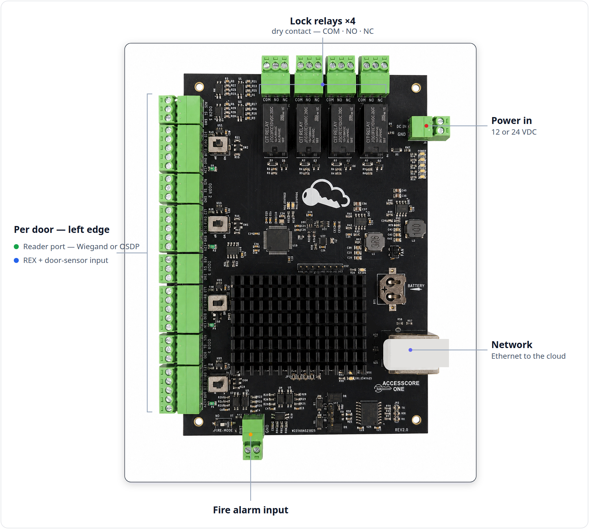
A. Network uplink (Ethernet)
The controller's primary connection to the CAK cloud is the on-board RJ45 Ethernet jack (ref J19, right edge of the board). It is a 10/100 port with integrated link/activity LEDs on the jack.
RJ45 connector
| Pin | Silkscreen | Function | Wire to |
|---|---|---|---|
| RJ45 (8P8C) | J19 | 10/100 Ethernet uplink | LAN switch / router, straight-through cable |
Use a standard straight-through Ethernet patch or structured-cable run from J19 to the building LAN switch or router. There is no crossover or special pinout — terminate to T568B like any other low-voltage data drop.
What the controller needs from the network
The controller reaches the CAK cloud outbound over the internet. It does not require any inbound port forwarding.
- DHCP by default. Out of the box the controller requests an address from the LAN's DHCP server. No IP is configured on the board.
- Static addressing is configured in software, not on the board. There is no DIP switch or jumper for IP settings. If the site requires a static address, set it in the controller's software configuration after it is online.
- Outbound internet to the CAK cloud endpoints must be permitted. On managed/firewalled networks, allow the controller's outbound HTTPS traffic and any addresses CAK publishes; do not place it behind a captive portal.
The controller does not need internet to operate — internet is only required to make configuration changes. With the node online, access is granted and denied from the node's stored database whether or not the internet is up. If the node itself goes offline, the control MCU falls back to a master card list until the node returns; events queue and sync on reconnect. See the Controller Overview for the architecture.
Networking checklist
:::caution PoE is NOT the power source The Ethernet jack does not power the board. The AccessCore One is powered by DC IN (12 or 24 VDC). If you feed a PoE-powered switch port into J19, the controller still will not power up — land DC on DC IN as described on the Power & Enclosure page. :::
- Run a wired drop to a switch. Do not rely on Wi-Fi for a controller — bridge to a wired uplink if wireless backhaul is unavoidable, but a controller should land on a wired, reliable LAN port.
- One straight-through cable, J19 to switch. No crossover.
- Confirm the link LED on the jack lights when the cable is connected and the controller is powered.
- Provide outbound internet (DHCP by default); set a static address in software only if the site requires it.
B. OSDP / RS-485 reader bus
The field RS-485 bus is the OSDP reader bus. There is no separate RS-485 screw terminal on the board. OSDP readers wire directly to the reader ports, using the D0/A pin as RS-485 A and the D1/B pin as RS-485 B, with each port's protocol jumper set to OP (OSDP).
OSDP readers land on the standard reader ports (refs J14–J17, Door 1–4); the D0/A pin is RS-485 A and D1/B is RS-485 B. Set each port's "OP / WD" jumper (refs S1–S4) to OP. The per-reader wiring procedure lives on the Wiring Readers page; this page covers the bus — topology and termination.
:::info Isolated, encryption-capable The OSDP/RS-485 transceiver on the AccessCore One is galvanically isolated (and ESD/surge protected on the reader data lines). Where the readers support it, OSDP runs Secure Channel for encrypted, authenticated reader communication. :::
Bus topology — daisy-chain only
Wire OSDP as a daisy chain (multidrop): the bus enters a device and continues out to the next. No star wiring and no stubs — a star or a long T-tap off the trunk corrupts RS-485 signalling.
- Use shielded twisted pair. Keep A (D0/A) and B (D1/B) on one twisted pair.
- Ground the shield at the controller end only. Do not ground the shield at the readers — grounding both ends creates a ground loop.
- Observe RS-485 polarity consistently: A → A (D0/A) and B → B (D1/B) at every device.

For OSDP/RS-485 cable distance, shielded twisted pair supports runs up to roughly 1200 m / 4000 ft as general industry guidance — defer to the reader manufacturer's published spec for the limit on a given device. (Wiegand readers, by contrast, are limited to roughly 150 m / 500 ft on 18–22 AWG; see Wiring Readers.)
Termination — both ends only
RS-485 must be terminated with 120 Ω at the two physical ends of the bus, and only there. The AccessCore One provides on-board termination via the "OFF / 120" jumper (near ref JP3).
- Set the controller's jumper to 120 when the controller sits at one end of the bus.
- Terminate the device at the far end of the bus too (120 Ω, per that device's instructions).
- Leave every intermediate device unterminated (OFF / no termination).
- A bus terminated in the middle, or terminated at three or more points, reflects and degrades the signal.
| Position | Termination | Use when the controller is… |
|---|---|---|
120 | ON (120 Ω) | …at one physical end of the OSDP bus |
OFF | OFF | …not at a physical end of the OSDP bus (terminate the two ends elsewhere) |
:::note No separate RS-485 terminal OSDP field wiring lands only on the reader ports and the "OFF / 120" termination jumper — there is no separate RS-485 screw terminal on the board. :::
Quick reference
- Cloud uplink: RJ45 J19, 10/100, straight-through to the LAN switch. DHCP by default; static set in software. Outbound internet only.
- Not PoE-powered: the board runs on DC IN — see Power & Enclosure.
- OSDP bus = reader ports in OP mode: D0/A = A, D1/B = B. No separate RS-485 terminal.
- Topology: daisy-chain, shielded twisted pair, shield grounded at the controller end only.
- Termination: 120 at both physical ends only; OFF on every intermediate device.
See also: Wiring Readers · Power & Enclosure · Terminal & Connector Reference · Controller Overview.