Power & Enclosure
This page covers powering the AccessCore One controller: the DC input, the real-time-clock battery, cooling fan, grounding, enclosure practice, and how to size and budget the supply. All power and system connectors live on the right edge of the board.
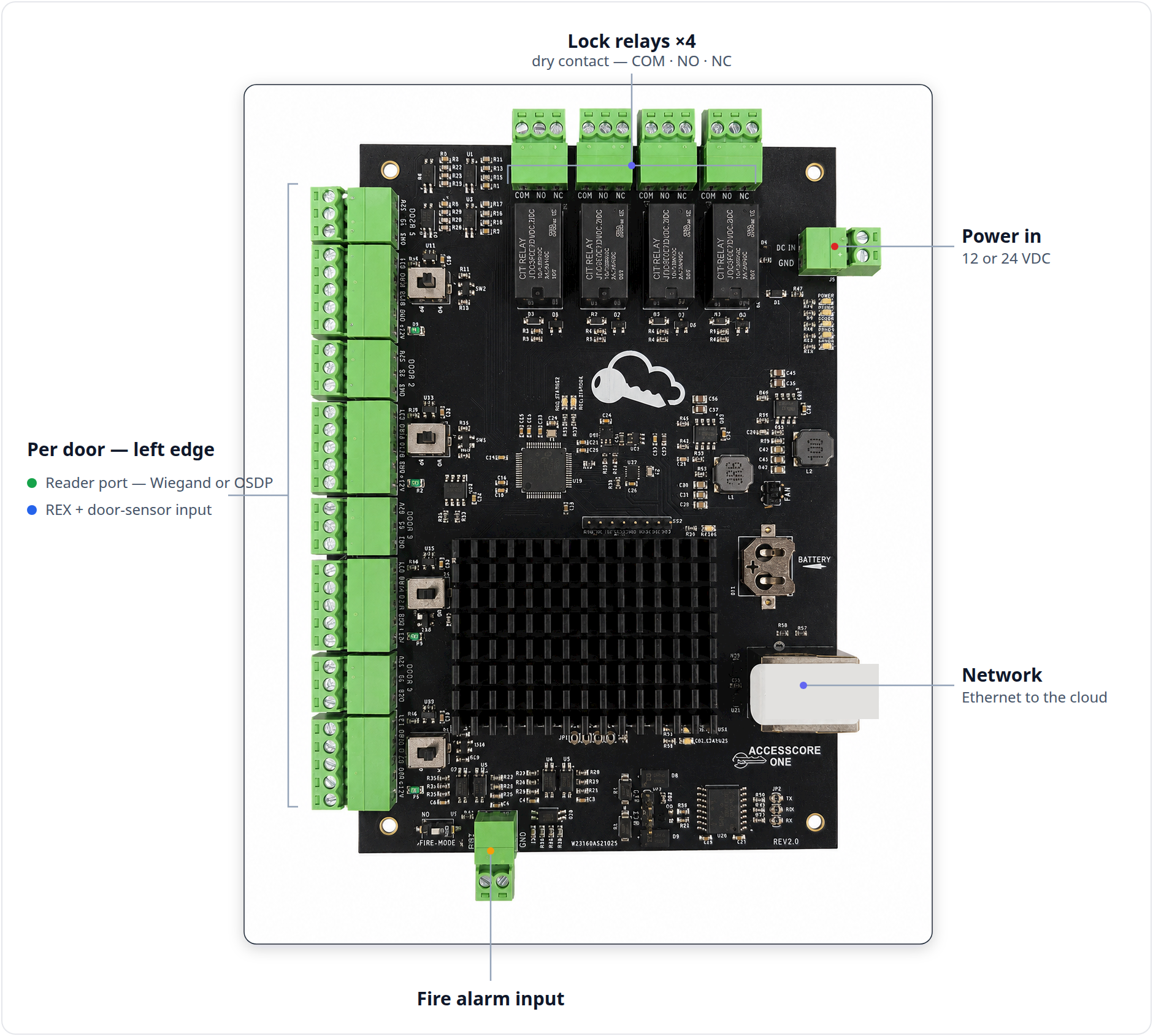
The controller runs on 12 or 24 VDC. The DC input is reverse-polarity protected (P-FET) and transient/TVS protected, but you must still observe polarity — the protection prevents damage, it does not make a backwards supply work.
Confirm polarity before applying power. Land the supply + (12 or 24 V) on DC IN and 0 V /
ground on GND. Never exceed the reader-port fuse budget (~0.75 A per port,
self-resetting PTC) when powering readers from the controller.
Power & system connectors (right edge)

DC IN / GND — main power input (ref J9)
| Pin | Silkscreen | Function | Wire to |
|---|---|---|---|
| 1 | DC IN | +12 V or +24 V DC input | + from the power supply |
| 2 | GND | 0 V / ground | 0 V / ground from power supply |
BATTERY — RTC clock battery (ref BT1)
The on-board BATTERY holder is a coin cell for the real-time clock — it is not an SLA standby-battery input. See Backup power & the clock battery below.
FAN — cooling fan (2-pin)
| Pin | Silkscreen | Function | Wire to |
|---|---|---|---|
| 1 | + | Fan +12 V | Fan + lead |
| 2 | − | Fan ground | Fan − lead |
The RJ45 Ethernet jack (ref J19) on the same edge is the network uplink, not a
power connector — see Networking & OSDP Bus.
Connect DC input
- Set the controller's power supply to 12 or 24 VDC. Do not power the board until wiring is verified.
- Land the +12 V conductor on
DC IN. - Land the 0 V / ground conductor on
GND. - Double-check polarity at the terminal before energizing. The input is reverse-polarity and transient protected, but correct polarity is still required for the board to run.
- Apply power and confirm the POWER LED (green) is lit. See First power-up.
Choosing and sizing the power supply
Size the supply for the controller plus every device drawing from it on that supply rail — not just the board alone.
:::info UL 294-compliant installs — use a listed battery-backup supply For a UL 294-compliant installation, power the controller from a UL-294-listed access-control power supply with battery backup, sized for the standby requirement. The listed supply carries the standby-power evaluation (battery, charger, AC-loss behavior); the controller runs on its backed-up 12 or 24 VDC output. Confirm the acceptable supply with CloudAccess Key. See Listing & Compliance. :::
What can draw from the controller's supply:
- The controller itself — the node, the control MCU, relays, status LEDs, and the clock.
- Readers powered from the reader ports — each reader port provides ~12 V output, protected by a self-resetting PTC fuse at ~0.75 A per port (refs F1–F4). Budget each reader's draw against that per-port limit. See Wiring Readers.
- A cooling fan on the
FANheader, if fitted.
:::caution Do not exceed the reader-port fuse Each reader port is PTC-fused at ~0.75 A. If a reader draws more than the port allows, the PTC trips and the reader loses power until it cools. Power high-draw readers from a separate fused supply rather than overloading a port. :::
Locks are budgeted separately
Lock power does not come out of the controller. The relay outputs are dry contacts — the board switches the lock's circuit but does not source lock current. You provide the lock's power supply and route it through the relay. See Wiring Locks.
Budget lock power separately from the controller supply. For multiple locks, or maglocks and strikes with meaningful current draw, use a dedicated lock power supply sized for the simultaneous load. Keeping locks on their own supply also keeps inrush and inductive noise off the controller rail.
A clean split is one supply for the controller (and its readers, within the per-port fuse budget) and a separate, appropriately sized supply for the locks. Confirm both supplies share a common ground reference where required by the device wiring.
Backup power & the clock battery
Standby (battery) backup is provided by the external power supply, not the board. For a compliant install the controller is powered from a UL-294-listed access-control supply with its own battery backup (see Listing & Compliance); the controller simply runs on that supply's backed-up output through a mains outage. There is no on-board SLA standby-battery input.
The board's on-board BATTERY holder is a coin cell for the real-time clock
(RTC) only. It keeps the controller's clock and event timestamps correct through
a full power loss — it does not power the controller or the locks. Replace it
like any coin cell if the clock drifts after long unpowered storage.
:::caution Maglocks and life-safety egress A maglock on an egress door must release on a fire alarm condition and on power loss. Do not let battery backup defeat fire-release or fail-safe egress behavior. Coordinate maglock power, battery backup, and fire release with the fire alarm system and the local Authority Having Jurisdiction (AHJ). See Fire Alarm Integration and Wiring Locks. :::
Cooling fan
The FAN header is a 2-pin, 12 V output marked + and −, intended for
active cooling of the node.
- A fan is optional but recommended in warm or sealed enclosures, where the node has limited passive airflow.
- Match fan polarity (+ / −) to the header.
- A 12 V fan rated for the enclosure conditions is sufficient; the header provides 12 V.
Grounding & enclosure
- Mount in a locked enclosure within the secured premises. Use a lockable enclosure rated for access-control / low-voltage equipment, with room for the board, the power supply, and field cabling, sited inside the protected (secured) area. A locked enclosure in the secured area is a UL 294-compliant installation condition — see Listing & Compliance.
- Keep low voltage separated from line voltage. Do not run the controller's low-voltage cabling alongside or through line-voltage (mains) wiring. Maintain separation per local electrical code.
- Ground cable shields and drains at the controller end only. Land shield /
drain conductors on the dedicated
GNDterminal block (bottom edge of the board). Grounding a shield at both ends invites ground-loop noise. - For shielded reader cable, ground the shield at the controller end only — see Wiring Readers.
Diagram placeholder — enclosure layout showing the controller, the listed power supply, and low-voltage / line-voltage separation.
First power-up
After wiring is verified and DC is applied:
- The green POWER LED lights — power is good.
- MCU STATUS 1 begins a steady ~1 blink / second heartbeat once the firmware is running.
- MCU STATUS 2 goes solid once the controller links to its node (it may blink briefly first while the link comes up).
If the POWER LED does not light, remove power and recheck the DC IN / GND
polarity and the supply output before continuing. For what each status LED means,
see the Status LEDs guide.
Related pages
- Controller Overview — board layout, LED legend, architecture.
- Wiring Readers — reader-port power and the ~0.75 A per-port PTC fuse.
- Wiring Locks — lock power, dry-contact relays, fail-safe vs. fail-secure.
- Terminal & Connector Reference — full connector and pin map.
- Hardware & Wiring — hardware landing page.