Terminal & Connector Reference
This is the single-page cheat sheet for the AccessCore One controller. Every connector, jumper, and status LED is listed below in silkscreen order, so you can wire the entire board from this page alone. For step-by-step procedures and deeper background, follow the cross-links to the dedicated pages.
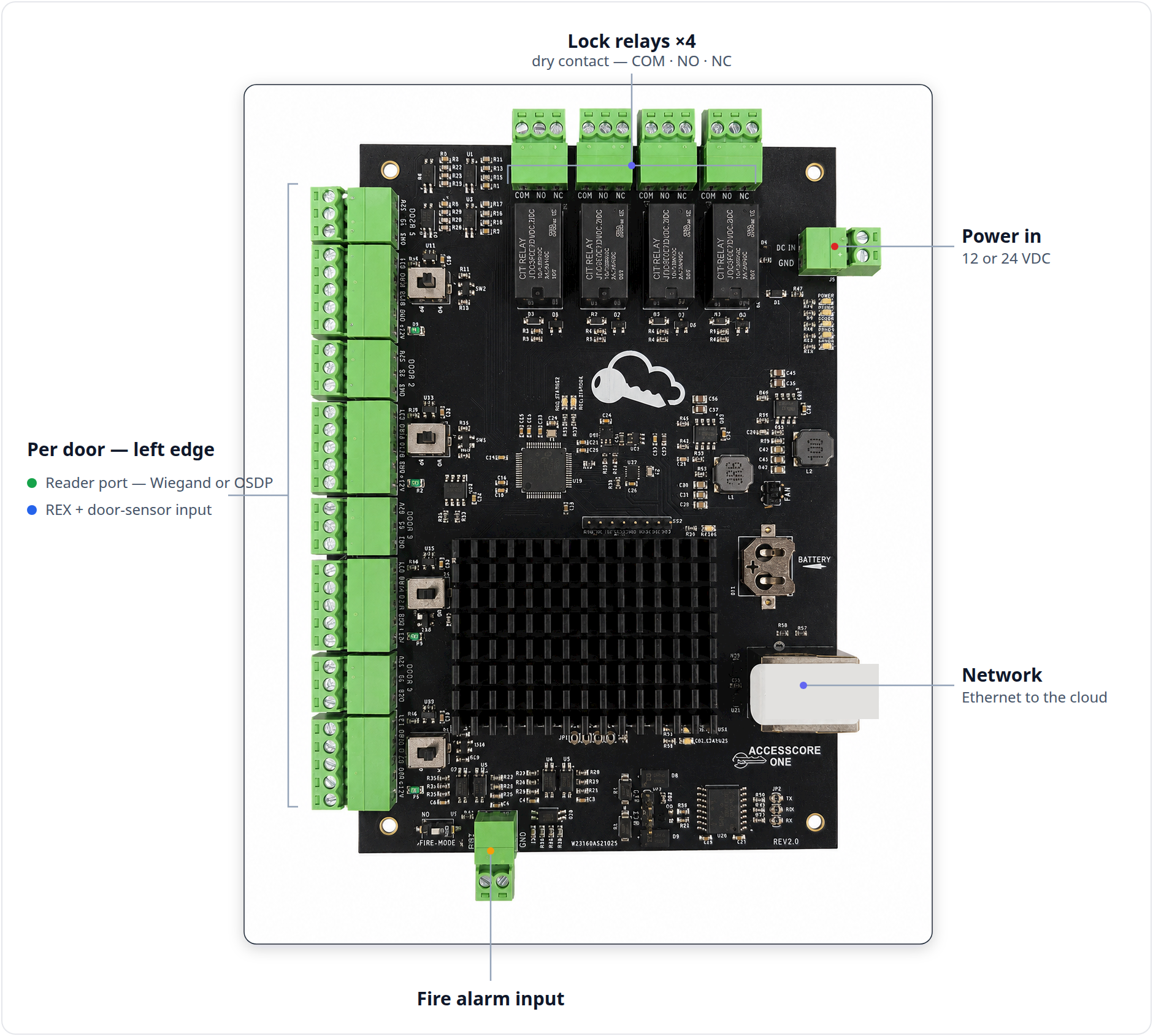
The controller has a capacity of 4 doors. Each door gets one reader port, one lock relay, and one 3-pin input port (REX + door sensor). Connectors are grouped by board edge: reader ports and door inputs on the left, lock relays across the top, power and Ethernet on the right, fire input and bus config along the bottom.
Print this page. Keep the board-map image and the connector tables in front of you while you land conductors. Every silkscreen string in the tables below matches the label etched on the board exactly.
Related pages: Controller Overview · Power & Enclosure · Wiring Readers · Wiring Locks · REX & Door Contacts · Fire Alarm Integration · Networking & OSDP Bus · Hardware & Wiring
Reader ports — J14–J17 (one per door)
Four 5-pin ports on the left edge, one per door:
| Ref | Door |
|---|---|
| J14 | Door 1 |
| J15 | Door 2 |
| J16 | Door 3 |
| J17 | Door 4 |
Silkscreen pin order (top to bottom) is identical on all four ports:
| Pin / Silkscreen | Function | Notes |
|---|---|---|
LED | Reader LED control output | Drives the reader's red/green LED line. |
D0/A | Wiegand DATA0 / OSDP RS-485 "A" | In OSDP mode this pin is RS-485 A. |
D1/B | Wiegand DATA1 / OSDP RS-485 "B" | In OSDP mode this pin is RS-485 B. |
GND | Signal / power ground | Common return for reader power and data. |
+12V | Reader power out, ~12 V | Self-resetting PTC fuse, ~0.75 A per port (refs F1–F4). |
The OSDP/RS-485 transceiver is galvanically isolated (ISO1450) and ESD/surge
protected (TVS + PTC) on the reader data lines. Set the per-port OP / WD jumper
to match the reader type — see Jumpers below and
Wiring Readers.
Door input ports — J5–J8 (REX + door sensor)
Four 3-pin ports on the left edge, each beside its reader port and labeled
DOOR 1..DOOR 4:
| Ref | Door | Silkscreen |
|---|---|---|
| J5 | Door 1 | RX1, S1, GND |
| J6 | Door 2 | RX2, S2, GND |
| J7 | Door 3 | RX3, S3, GND |
| J8 | Door 4 | RX4, S4, GND |
Silkscreen pin order (top to bottom):
| Pin / Silkscreen | Function | Notes |
|---|---|---|
RXn | Request-to-Exit (REX) input | Dry contact between RXn and GND. |
Sn | Door position Sensor (DPS / door contact) | Dry contact between Sn and GND. |
GND | Common ground / return | Shared return for both inputs on this door. |
:::danger Never back-feed these inputs
Both inputs are optically isolated, dry-contact inputs. Connect a dry contact
only between the input pin and GND. Do not apply any external voltage to
RXn or Sn — doing so can damage the isolator. See
REX & Door Contacts.
:::
Lock relay outputs — J1–J4 / DR1–DR4 (top edge)
Four 3-terminal outputs across the top edge, one per door, grouped and labeled
DR1..DR4:
| Ref | Group | Door |
|---|---|---|
| J1 | DR1 | Door 1 |
| J2 | DR2 | Door 2 |
| J3 | DR3 | Door 3 |
| J4 | DR4 | Door 4 |
Each output is a Form C / SPDT dry contact set. Silkscreen pin order:
| Pin / Silkscreen | Function | Notes |
|---|---|---|
COM | Relay common | Route the lock supply through COM. |
NO | Normally-open | Open when idle/locked; closes when energized. Use for fail-secure devices (electric strikes). |
NC | Normally-closed | Closed when idle; opens when energized. Use for fail-safe devices (maglocks). |
:::caution Dry contacts — no voltage out
The board does not push voltage out of these pins. Route the lock's own power
supply through COM + NO (fail-secure) or COM + NC (fail-safe). Each relay
has on-board MOV/varistor inductive-spike suppression, but you must still suppress
the lock load at the device and respect the relay rating — use an interposing
relay for high-current locks. See Wiring Locks.
:::
:::danger Fail-safe egress and life safety
Maglocks (fail-safe) must release on fire alarm and on power loss. Wire
maglocks on COM + NC and coordinate egress release with the fire alarm system
and the local AHJ / fire code. See Fire Alarm Integration.
:::
Power & system
DC IN / GND — J9 (main DC input)
| Pin / Silkscreen | Function | Notes |
|---|---|---|
DC IN | +12 V / +24 V supply input | 12 or 24 VDC. Reverse-polarity protected (P-FET) and TVS/transient protected. |
GND | 0 V / ground | Supply return. |
BATTERY — BT1 (RTC clock battery)
| Pin / Silkscreen | Function | Notes |
|---|---|---|
BATTERY (BT1) | RTC coin cell | Backs up the real-time clock through a power loss. Not a standby-battery input — backup power for access comes from the external listed supply. |
FAN (node cooling)
| Pin / Silkscreen | Function | Notes |
|---|---|---|
+ | Fan +12 V | 12 V fan for active cooling of the node. |
− | Fan return | Optional but recommended in warm/sealed enclosures. |
Ethernet — J19 (network uplink)
| Connector | Function | Notes |
|---|---|---|
| RJ45 (J19) | 10/100 network uplink | Integrated link/activity LEDs. Primary connection to the CAK cloud. |
See Power & Enclosure for supply sizing and battery selection, and Networking & OSDP Bus for the network uplink.
Fire alarm input — FIRE / GND (J13)
2-pin dry-contact input from the fire alarm panel / relay, on the bottom edge:
| Pin / Silkscreen | Function | Notes |
|---|---|---|
FIRE | Fire alarm interface input | Dry contact from the fire alarm panel / relay. |
GND | Return | Common ground for the fire input. |
Select the contact convention with the FIRE_MODE (NO / NC) jumper — see
Jumpers. On a fire condition the controller drives the door relays to
the unlock state so doors release for egress.
:::danger Life-safety path This is a life-safety circuit. Coordinate it with the fire alarm system and the local AHJ / fire code. Maglocks on egress doors must release on fire alarm and on power loss. See Fire Alarm Integration. :::
Ground block — GND (bottom edge)
| Terminal | Function | Notes |
|---|---|---|
GND | Dedicated ground terminal block | For cable shields/drains and common grounds. Ground reader-cable shields at the controller end only. |
Jumpers
| Jumper / Silkscreen | Ref | Position | Effect |
|---|---|---|---|
OP / WD (per reader) | S1–S4 | WD | Wiegand reader. |
OP / WD (per reader) | S1–S4 | OP | OSDP reader (RS-485). OSDP A = D0/A pin, OSDP B = D1/B pin. |
FIRE_MODE (NO / NC) | — | NO | Fire input treated as normally-open. |
FIRE_MODE (NO / NC) | — | NC | Fire input treated as normally-closed. |
OFF / 120 (RS-485 termination) | near JP3 | 120 | 120 Ω termination ON — use on the device at the far/last end of the bus. |
OFF / 120 (RS-485 termination) | near JP3 | OFF | Termination off. |
:::note OSDP bus termination
The field RS-485 bus is the OSDP reader bus — the D0/A and D1/B pins of
any reader port set to OP. There is no separate RS-485 screw terminal; OSDP
readers wire to the reader ports. Terminate the bus at both ends only. See
Networking & OSDP Bus.
:::
Status LEDs
| LED | Meaning |
|---|---|
POWER (green) | Power good. |
| MCU STATUS 1 — green | Heartbeat: 1 Hz = firmware running; off = no boot (check power); 5 Hz fast = fault. |
| MCU STATUS 2 — red | Node link: solid = online; off = node not seen yet; 1 Hz = offline; 5 Hz = recovering. |
| Node STATUS — green/red | Bluetooth setup: red↔green alternating while a setup session is connected; otherwise off. |
| Node activity — orange | Node activity light. |
| Reader LED (per door) | Solid = door held open; brief flash = access denied. |
During an OTA update, MCU STATUS 1 (green) & STATUS 2 (red) alternate fast in anti-phase (~5 Hz) — do not power-cycle. See the full Status LEDs guide.
First power-up / commissioning checklist
Work through these in order. Do not apply power until step 9.
:::note Compliant installs For a UL 294-compliant installation, also observe the four conditions on the Listing & Compliance page: a locked enclosure in the secured premises, a UL-294-listed battery-backup supply, lock outputs through a UL-listed fused relay/output board, and an independent hardware egress power-interrupt for push-to-exit and fire release. :::
- Mount and ground. Secure the controller in its enclosure (locked, and
within the secured premises, for compliant installs) and bond the
chassis/enclosure ground. Land cable shields and common grounds on the
GNDblock. - Land DC IN / GND — do not power yet. Connect the 12 or 24 VDC supply: the
+ lead to
DC IN(J9), 0 V toGND. Leave the supply off / unplugged for now. (Battery and fan, if used:BATTERYBT1 observing+/−;FANobserving+/−.) - Wire readers and set
OP / WD. For each door, land the reader on its port (J14–J17) per the pinout:LED,D0/A,D1/B,GND,+12V. Set that door'sOP / WDjumper (S1–S4) —WDfor Wiegand,OPfor OSDP. See Wiring Readers. - Wire locks — fail-safe vs fail-secure. Route the lock supply through the
relay (J1–J4 / DR1–DR4): use
COM+NOfor fail-secure electric strikes,COM+NCfor fail-safe maglocks. Suppress the lock load; use an interposing relay for high-current locks. See Wiring Locks. - Wire REX and door contacts. On each door input port (J5–J8) connect a dry
contact from
RXntoGNDfor REX and fromSntoGNDfor the door sensor. Apply no external voltage. See REX & Door Contacts. - Wire the fire input and set
FIRE_MODE. Land the fire alarm dry contact onFIRE/GND(J13) and set theFIRE_MODE(NO / NC) jumper to match the fire panel output. Coordinate with the AHJ. See Fire Alarm Integration. - Connect Ethernet. Plug the 10/100 uplink into the RJ45 (J19). See Networking & OSDP Bus.
- Set OSDP bus termination. On any OSDP bus, set the
OFF / 120jumper to120only on the device at the far/last end of the bus;OFFeverywhere else. Terminate both ends of the bus only. - Apply power. Turn on the 12 or 24 VDC supply.
- Confirm the status LEDs. Verify the green
POWERLED is lit, MCU STATUS 1 is blinking its ~1/sec heartbeat, and MCU STATUS 2 goes solid (node link up). - Test each door. For every door, verify: a credential read at the reader, a REX activation, the door-position sensor (DPS) state changes as the door opens/closes, and that a fire condition drives the relay to the unlock state and releases the door for egress.
Quick troubleshooting
| Symptom | First things to check |
|---|---|
No POWER LED | Verify supply present and 12 or 24 VDC; confirm DC IN polarity at J9 (input is reverse-polarity protected, so a reversed lead reads as no power). |
| Reader dead / no power | Check the per-port PTC fuse (F1–F4); confirm +12V and GND landed; verify the OP / WD jumper matches the reader type. |
| Relay clicks but lock doesn't move | Check the lock power path through COM; confirm NO vs NC matches the lock's fail mode; verify lock supply and current capacity / interposing relay. |
| Door always shows open (or always closed) | Check the DPS dry contact on Sn/GND and the contact convention (N/O vs N/C); confirm wiring to the correct door input port. |
| OSDP reader offline | Confirm OP jumper set; check OSDP A on D0/A and B on D1/B (not swapped); verify OFF / 120 termination at both bus ends only; confirm the reader's OSDP address. |
For deeper diagnostics and per-subsystem detail, see the sibling pages: Controller Overview · Power & Enclosure · Wiring Readers · Wiring Locks · REX & Door Contacts · Fire Alarm Integration · Networking & OSDP Bus · Hardware & Wiring.